![Highland_logo_1millionmiles_Brandmark_White-1.png]](https://24210048.hs-sites.com/hs-fs/hubfs/Highland_logo_1millionmiles_Brandmark_White-1.png?width=40&height=40&name=Highland_logo_1millionmiles_Brandmark_White-1.png)
Towing
When it is necessary to tow the vehicle, make sure the instructions below are closely followed to prevent damage to the vehicle. When towing or pushing the vehicle, regardless of the distance or speed traveled, either disconnect the driveshaft at the rear axle and support it as necessary, or remove the axle shafts.
Do not tow an unbraked vehicle if the combined weight of both vehicles is more than the sum of the gross axle weight ratings (GAWR) of the towing vehicle. Otherwise brake capacity will be inadequate, which could result in personal injury or death.
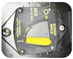
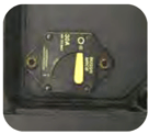
- Prior to towing, shut off the contactor to disable the HV system
- Turn lever clockwise to switch contactor off
Tow Vehicle Capacity
Optimal has determined the curb weight of the Optimal S1 Low Floor Bus to be 12,000 lbs, and 12,000 lbs for the G1. Optimal suggest that the towing equipment has a minimum 20% safety margin. Tow trucks should have the capacity to tow 14,000 lbs for the S1 and 16,800 lbs for the G1.
DO NOT TOW FROM THE FRONT. Severe damage may occur to the electric traction motor that drives the rear wheels. Towing with the rear wheels on the ground may cause an unintended generation of high voltage throughout the system.
Tow with rear wheels off the ground
- A flatbed truck is the recommended method for transporting a disabled bus. If towing is necessary, the rear wheels must be off the ground either towed from the rear or with the rear wheels on a dolly
- Towing from the front is not recommended and may cause severe damage to the traction motor. When towing the bus, the tow truck lifting device must contact only the frame rails or the rear wheels
- If the bus is towed or hauled with the rear of the bus forward, secure the primary dual panel entrance door to prevent it from opening. A strong strap or bungee cord is sufficient. Otherwise, towing the bus backward, rushing air can catch the front door leaf and pull the door open, likely causing damage to the door panels or the opening mechanism
- Secure the charging port door with masking tape to prevent wind damage
Lifting and Hoisting
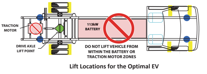
To avoid damage to the vehicle battery pack and traction motor, do not position any lifting equipment under either of these critical components
When servicing the vehicle, refer to the figure below to identify acceptable lifting points
- Yellow areas represent lift locations for the mobile column lift system (four-post style)
- Blue areas indicate locations under the chassis rail jacks can be positioned for lifting the vehicle with a portable floor jack
Lift points and jack stands
Place jack under the frame rails at the locations identified by the blue circles in the illustration above.
For additional details on Optimal buses, please refer to the High Voltage Safety Training 101 & Operator's Guide