![Highland_logo_1millionmiles_Brandmark_White-1.png]](https://24210048.hs-sites.com/hs-fs/hubfs/Highland_logo_1millionmiles_Brandmark_White-1.png?width=40&height=40&name=Highland_logo_1millionmiles_Brandmark_White-1.png)
Cold Weather
Ensure your buses are prepared for inclement weather, especially in temperatures below 30° to avoid turtle mode* and conserve battery life.
If a vehicle has been parked for an extended period in cold weather, always check to be sure all wheels are rolling free (brakes are not frozen) when starting out. Always clean accumulated ice and snow from brake linkage.
Winter pre-trip routine
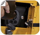
- Unplug the bus from the charger
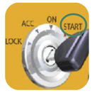
- Turn the bus on completely, including cabin heaters
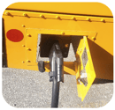
- Plug the bus back into the charger
- Let the bus warm up for 10-15 minutes
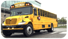
- Unplug the charger and start the route
*Turtle mode: Drive power is restricted. Typical causes for this condition include the high-voltage batteries not being sufficiently charged or being at its operating temperature limit, such as in very cold outdoor temperatures.
Tips to Increase Range
To increase the range of the bus
Regenerative braking
During regenerative braking, the drive motor converts the momentum of the moving vehicle into electrical energy, which is stored in the high-voltage batteries
- Applying the bus brake pedal will reduce the amount of regenerative braking energy that is recovered. When safe to do so, use the regenerative braking function to recover energy. This will extend the total vehicle range
Do not use the deceleration effect of regenerative braking as a distance control system. Always be ready to brake and stay a safe distance away from the vehicle in front
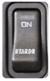
- Use the RTARDR switch to turn “ON / OFF” regenerative braking
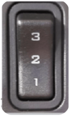
-
Selects level or regenerative braking strength
-
Lowest level of regenerative braking
-
Moderate level of regenerative braking
-
Highest level of regenerative braking
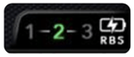
-
- The selected mode will be identified in green on the cluster
Regenerative braking can be limited if the battery state of charge is high, or if the battery is cold. System will not allow HV batteries to be overcharged.
Charging Tips
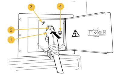
Charge port
- Charging plug
- Release button
- Emergency charging plug release cable
- Charge interface button
LED Codes
 |
Blue - Charging plug successfully connected and unlocked OR charging plug is ready to be removed |
 |
Green flashing - Charging in progress |
 |
Yellow - Charging plug is connected but charger is not active |  |
Green - Charging is complete. Charge interface button needs to be pressed to unlatch |
 |
Yellow flashing - The vehicle is not ready to charge. The parking brake must be set and the transmission must be in Neutral (N) |  |
Purple flashing - Discharging in progress (if equipped) |
 |
White - Charging communication in progress |  |
Purple - Discharge complete (if equipped) |
 |
Green pulsing - Low power charge mode is active to sustain High-Voltage auxiliaries (if equipped) |  |
Red - A bus or charger error has been detected |
Start a charging session
The bus must be stationary, in Neutral (N), and have the parking brake set to enable charging.
- Park the vehicle so the charge port is within reach of the charging cable, switch the vehicle OFF, and set the parking brake
- Ensure that the 12V disconnect switch is in the ON position. The disconnect switch must be in the ON position in order to charge the batteries
- Open the access door to the charge port
- Insert the charging handle straight into the vehicle charge port. An audible click should be heard when the charging plug is fully engaged
- The LED light around the charge interface button will illuminate BLUE to indicate the charger to vehicle connection is secure
- Blinking GREEN indicates charging is in progress. Solid GREEN indicates charging is complete
Why isn’t the bus charging when the charger is plugged in?
If the charging process was not started, do the following:
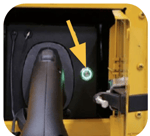
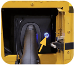
- Press the release button (2) and insert the charging plug completely into the charge port. If the charging plug is heavy, lift the plug in the charge port slightly so that it will lock into position. An audible click should be heard when the charging plug is fully engaged
- The LED light around the charge interface button will illuminate BLUE to indicate the charge to vehicle connection is secure
- The vehicle and charger will begin the interface process, which can take up to 60 seconds to complete
- The LED indicator on the button will begin to flash GREEN. The speed of the flashing indicates the vehicle State of Charge (SOC). As the vehicle approaches a full charge, the frequency of the flashing slows. When fully charged, the LED stays on solid GREEN
End a charging session
- Push the charge interface button located in the charge port area to cancel the charger to vehicle interface. After 15 to 60 seconds the LED indicator around the button will turn BLUE
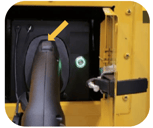
- Push the button (1) on the charging handle and remove the charger handle from the charge port. Place charger handle back on charging stand and move charging cord out of the way of people and vehicles
End the charging process before disconnecting the vehicle charging plug from the charge port. An ongoing charging process can be ended at any time by following the process above and removing the charging plug
For additional details on IC buses, please refer to the IC Bus Operations and Maintenance Manual