![Highland_logo_1millionmiles_Brandmark_White-1.png]](https://24210048.hs-sites.com/hs-fs/hubfs/Highland_logo_1millionmiles_Brandmark_White-1.png?width=40&height=40&name=Highland_logo_1millionmiles_Brandmark_White-1.png)
Daily Tips
Personal Protective equipment (PPE)
- Class 0 electrical insulating gloves (red label)
- Re-certify every 6 months
- If new pair, never used, the printed date is good for 1 year
- Leather over gloves
- Electrical Hazard (EH) rated safety shoes or boots
- Safety glasses or goggles
- Lockout/Tagout equipment
Maintenance Guidelines
When servicing the bus, always:
- Turn the key to the OFF position unless the procedure calls for it
- Set the parking brake and install wheel chocks
- Use support stands, not a jack, whenever you must be under a raised vehicle. • Do not smoke
- Wear safety glasses for eye protection
- Do not work on brakes unless the proper precautions have been taken to avoid inhaling friction material dust
- Do not wear loose clothing, hanging jewelry, watches or rings; tie up hair when around rotating machinery
- Avoid contact with hot metal parts; allow hot components to cool before working on them
- Repair or replace any defects that were revealed during inspection, prior to operating the vehicle
- High voltage can result in serious injury or death. Never touch the battery terminals with your fingers, tools, jewelry or other metal objects
- The high-voltage batteries can burn. The high-voltage batteries must never be exposed to fire, sparks, or open flames. Always handle the high-voltage batteries with care to prevent damage and fluid leakage
Maintenance instructions
Brake system
At regular intervals, inspect the entire brake system
- Rubber components for deterioration. Replacement intervals vary according to environmental severity and time in service
- Condition of rotors / drums, brake chambers, and slack adjusters
- System for air leaks
- Hose or pipes for corrosion, damage, deterioration
- Operation of service and parking brakes
Heater and coolant hose inspection
- Check coolant level as part of the daily inspection
- Check coolant concentration per coolant manufacturer requirements
- Perform a visual and touch inspection of all hoses. Hose inspection process is to include all body, interior and under body, hoses
- Check heater and coolant systems for signs of cold and hot leaks
- Pay attention to the hose ends and contact points that will typically show early signs of hose failure. Observe the area around all hoses for signs of leakage
- Synthetic rubber can oxidize and harden over time. Squeeze the hose to make sure it is pliable. Entire hose length should have a consistent feel and appearance
- Many times hoses will fail from the inside. A hose that appears in good condition can fail due to deterioration of the inner hose and reinforcement. This type of deterioration can sometimes be detected during pressure testing
- Cracks, blisters, or splits in the hose outer cover are the most visible signs of hose failure
- Pressure test complete heater and cooling system annually. Test should be completed while performing hose inspection to allow all hoses to be observed for bulges and leaks
High voltage components
Lifting
IMPORTANT
Due to the inherent design and setup of drive on hoists, special precautions related to electric vehicles should be noted
WARNING
Some components located under the bus may be damaged if the hoist height or drive on angle is not monitored during vehicle loading. In addition, obstacles located in the center portion of the lift may contact high voltage cables or shielding underneath the vehicle.
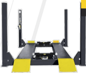
- Before using a drive on hoist, ensure the hoist is lowered all the way to the ground
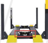
- Ensure there are no obstacles that may contact HV cables or shielding underneath the vehicle
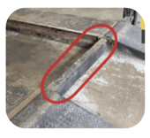
- Center section of hoist may still contact vehicle if drive on angle is too steep
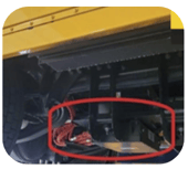
- Please pay special attention to HV cables and shielding located towards the rear of the bus
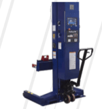
- Recommended lifting hoist is a column style host with a
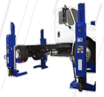
minimum of 14,000 lbs. lifting capacity per column
12V Battery Jump
If the 12V battery system has low voltage, the battery indicator will display on the instrument cluster, it may illuminate red. If the battery indicator is illuminated, the vehicle will not go into high voltage drive mode and the drive enable indicator will not illuminate, preventing the vehicle from starting.
If the low voltage battery system is less than 11 volts measured at the batteries, the system voltage is low and many of the control modules will not power up. In this situation, the 12V battery condition can be corrected by simply charging the 12V batteries or installing a 12V battery charge pack to the low voltage batteries.
IMPORTANT
In the event of charging a fully depleted vehicle, connect an approved 12V battery charger to the 12V battery system. The 12V battery system must have enough charge to wake-up the high voltage control system to enable charging. If the high voltage batteries have been depleted completely, they may not accept charge with being reset
WARNING
To prevent personal injury and/or death, or damage to property, whenever disconnecting 12V battery terminals, always disconnect the ground terminal first. When reconnecting, always connect the ground terminal last. Failure to follow this procedure could also result in a short to ground
- Open the 12V battery access door and turn the disconnect switch to the OFF position
- Using a 6 amp minimum jump box or battery charger, carefully connect the cable clamps to the proper terminals (positive to positive and negative to negative). Do not allow clamps to touch each other or the other terminals
- Wait five minutes to allow the bus batteries to build an initial charge
- Leave the cables connected and turn the 12V disconnect switch to the ON position
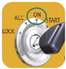
- Turn the ignition switch to the ON position
- Check to ensure that the parking brake is engaged
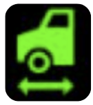
- Turn the ignition switch to the Start position and release. The power ON process may take up to 1 minute. The HV enable indicator will illuminate green
- Allow the low voltage status to clear then disconnect the charging cables
- Close the access door
For additional details on IC buses, please refer to the IC Bus Operations and Maintenance Manual